! ! WARNING ! !
Above is Zulu Time!!


Capsule modular build.
P/ During the design of the Capsule construction it came apparent that there was a need for a modular way of building, meaning that the exterior and interior panels must be able to be replaced without weaken the integrity of the structure. This is necessary, in case of damage to these panels. And also to be able to perform maintenance to the systems inside the Capsule.
S/ The Capsule will consist of two main parts, being the framework, and the (interior and exterior) panels. The thickness of the framework is directly proportional to the thickness of the soundproof isolation. By using a framework, all of the forces acting upon the Capsule will be evenly transferred.
The Capsule locking system.
P/ The Capsule has halve way his structure a split line. The framework must be able to be split in two parts so the Capsule can open and close to gain access inside. When these part are joined again the integrity of the complete frame work structure must be ensured.
S/ A set of line-up pins and locking hooks are installed at specific location all around the interface section of the Capsule. The locking hooks can only line up after the line-up pins get lined up. Then the hooks lock the two halves together. The design of these hooks are very similar to the ones of airplane cargo bay door hooks.
Gimbal Lock.
P/ Gimbal lock. In case of emergency caused by a TEF (Total Electrical Failure) the gimbals can free rotate. This is done to be able to get all gimbals to go to there horizontal starting position. But whenever gimbals can free rotate, the inner and support ring can align with the outer ring 90°, so vertical. This can remain like that, this is what they refer to as Gimbal Lock.
S/ In aviation a TEF became more and more a real threat, because of the fact that more systems inside modern airplanes were controlled or even completely electronic. In case of a TEF these systems would became dead, with all consequence off course. This is in some systems not a big issue like in-flight entertainment for example, but some systems need to stay active, think of Fly-By-Wire. Powered by an alternative power source. This can be done by batterys, solar power or via kinetic energy transferred to electric power. An example of this is the dynamo on your bicycle. In aviation this is known as a RAT which stands for Ram Air Turbine.
The most efficient solution would be to use battery power as a back-up. But this is only half of the solution, because batteries and there build-in chargers can also fail. I need a fail safe back-up system to be able to get the SVS completely back in his starting position. Only then this sim can be used by only one person, even in case of a TEF!! Magnets work without any power. In fact you could look at it as it were pieces of metal which stored a massive amount of electric power already.
The gimbal ring are therefore equipped at specific locations with very strong magnets. But these magnets may only operate in case of a TEF emergency. Therefore the magnets are isolated via an electro magnet working against to strong pulling springs, when power is supplied to the SVS. So whenever the power is lost, the isolation PVC plate is pulled out of between two magnets by use of these pulling springs, and when two magnets meet those rings are locked in position. This is a good solution for locking the ring together, preventing them to go to gimbal lock while still moving under their own inertia. But what if the rings are static at the moment the SVS experiences a TEF? In that case there is no inertia! We need something more, but what?
Lets resume what weve got so far;
- battery power to move the rings,
- magnets to lock the rings in their correct position.
Nice , but not enough! To be able to make this system fail-safe we need a power source of which we can be sure it will be there in case we need it. The only thing you can be sure of is, that YOU are there. What if,.. you could transfer the needed power from inside you to the sim. So transfer kinetic energy to electric power. As last resort the cockpit is equipped with a hand-alternator of 30 Watts/12volts, supplying this to the static inverter 12V-220V.
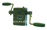
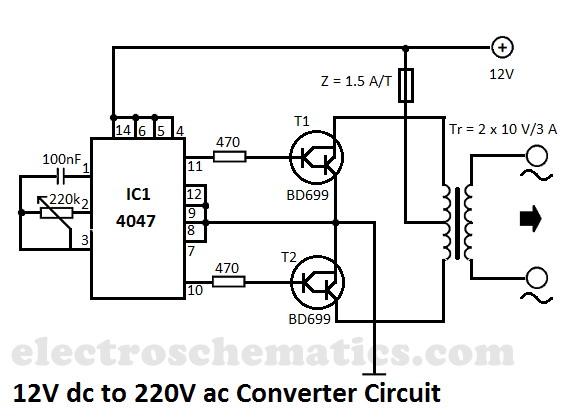
This inverter in turn supplies this power to the EMDUs which move the gimbal rings to the horizontal starting position. When these rings line-up they give a green locked light inside the cockpit when the gimbal ring locks have moved over and locked them in place. Now we have a system thats fail-safe, giving the SVS the ability to be operated by a single person being the pilot, even in case of an emergency situation. 100% save!
Article last modified on 04/02/2012

|
|
|
(c) 2004 www.simbuilder.be Created by See3D.be |
||