! ! WARNING ! !
Above is Zulu Time!!
 |
English |
|||
ATA 24
Electrical Power.
Electrical power an board an airplane is used for several things, to be able to fly the plane, to monitor the flight. To entertain the passengers, with movies music or just to warm food or refrigerate drinks. Where does this electrical power come from to operate all these systems?
Every engine is equipped with a Generator or Gen that is mounted on the accessory gearbox, further is this chapter you can find more info about this.
The Gen will supply AC power or Alternating Current to the planes electrical system. But, different to the AC power you have at your home being: 220Volt 50Hz or 110Volt 60Hz the airplane systems operate for some part on 115Volt with 400Hz!!!
Some systems need three phase power other only a single phase.
Depending upon which airplane, the number of Gen's will be 1,2,3 or more in the complete system. Let say the plane haze 2 engines and an APU or Auxiliary Power Unit (see ATA 49 for detail), this would mean that the plane haze two Gen's one on each engine and a third on the APU. So a total of three Gen's in the complete system.
The Gen's on the engines are the main suppliers of electrical power to the planes systems, the APU Gen is infect a back-up should any fault occur during flight the APU Gen can then be selected to supply power if needed. Also the APU is used on the ground in case there is no ground power supply available.
NOTE: The APU can be used during the complete flight, providing that the APU is build to do so, or under a specific flight level.
When the aircraft is at the gate there is a cart used consisting of a large/strong Diesel engine connected to a Gen, called a ground power supply. This ground power supply is at modern airports build in the tarmac near the nose of the plane this to cut down on fumes and noise, and this is quick and easy in use different to the ground power-cart which haze only got the advantage of being Mobil!
To be able to supply DC or Direct Current to the distribution systems the airplane is equipped with a device called a Transformer Rectifier or TR. This device turns AC 115/200 Volt 400Hz into DC 28/26 Volt. This way the Gen's can supply DC power via these TR's.
Battery's.
In case of emergency or also know as a total electrical failure there are 1 or more battery's to supply just enough power to the emergency flight instruments and flight systems. Providing that the electrical system is intact and haze not suffered any damage due to a bomb or something.(Let's hope so!!!) Some plane's have one battery others have three. Some use these for both the main systems as well to be able to start the APU without any ground power supply.
Gen's an CSD's.
A Gen haze to turn at a constant RPM (Revolutions Per Minute) to be able to supply a constant 400Hz. This is accomplished by use of a Constant Speed Drive or CSD, this device also mounted on the accessory gearbox supply's +/- 6000 RPM to the Gen. This is possible by a complex and brilliant system of gearwheels. All mounted in site a large heavy weight assy.
Simbuilder:I hated it when we had to change one of these things, because of the weight and the stupid shape of the thing. It's a bitch changing it, belief you me!
IDG, the newer CSD/Gen.
The CSD is an old way to maintain 6000 RPMs, the component used now is an IDG or Integrated Drive Generator. Its an CSD and a Gen combined in only one unit, which haze the big advantage that its smaller and not so heavy as the CSD/Gen combination. As a result this unit is easier and quicker to be replaced.
Only downside is that when ever the one part fails you have to change both parts because both are part of one unit, think about the costs adding here.Summery:
The engine drives the accessory gearbox, on this gearbox is the CSD mounded, the CSD's in turn driven by this gearbox will drive the Generator at a constant RPM of 6000, making it possible to uphold the 400Hz to supply the plane's electrical systems.
Build-in Safety Features:
Within the system there are some safety features build-in, for instance: let's assume a CSD or a Gen is not working correctly, during the constant system check the Current and Hertz is checked and monitored, in case of a fault with the CSD or the Gen. After this fault is detected by one or more of these parameters, because it will go out of limits, the system will automatic reject the faulty Gen or CSD for that matter and if the system is able to determine what the fault is, it will indicate this at the flight deck.
For instance: a high oil temp light, possible caused by a low oil level. Less oil to absorb the temperature gives a higher temp for the remaining oil, logic. And if this temp gets to high the CSD will trip-off to protect itself and the rest of the engine. This with visual warnings, like a pop-out at the CSD and a warning light at the flight deck together with an aural warning telling the crew something is happened. To be able to determine why it happened, maintenance personnel will carry out some checks.
The trip-off of the CSD's:
This is a build-in feature to protect the CSD of internal damage due to low or high oil level. The tripping-off is infect a mechanical clutch inside the CSD that disconnects the generator from the accessory gearbox, stopping it from turning and driving the Gen which in turn will stop supplying electrical power to his part of the system.
In most cases after a check done by maintenance personnel of the CSD and his oil level he will be reconnected manually, by pulling the reconnection lever on the CSD. This is only allowed when the engine is NOT turning!
This is why, when this happens at the gate, the engine has to come to a complete stop.It goes without saying that especially now with the modern technology used in the newer airplanes electricity is the most important on the plane, no electric's = no nothing! Due to the fact that modern planes have to meet a higher standard in flight safety, they are equipped with several computers, like the TCAS system for example, to be able to meet these standards. But then we have to be curtain the electrical system is fail-safe, by building redundancies in the system. One of these back-ups is the RAT or Ram Air Turbine.
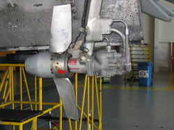
Ram Air Turbine.
The RAT is a small propeller that can be dropped down out of the bottom site of the wing and depending upon which airplane it can deliver hydraulic power only or both hydraulic and electric power, this via a hydraulically driven emergency generator. Logically a fly-by-wire plane will have both, while a plane with cable operated flight controls will probably have only hydraulic power coming from the RAT. This device is only used during an emergency!
The RAT of a Boeing 757
NOTE: a RAT will only deliver hydraulic power, the electrical power is generated via an emergency hydraulically driven generator. So in fact the RAT consist only of a hydraulic pump with a propeller mounted on the front, which gets turned by the air that passes while the airplane flys trough the air.
The working principal is very easy, infect you could compare it to a windmill, but instead of using the wind power to grind the grain, its used here to drive a hydraulic pump.


Article last modified on 10/06/2015

|
|
|
(c) 2004 www.simbuilder.be Created by See3D.be |
||